
Aerodynamics is widely accepted as the most critical feature of modern F1 design. Engineers often bend over backwards to allow for tighter bodywork on the car, or to create a wing that generates more downforce. To evaluate the viability of a design, engineers need ways of directly measuring and/or simulating its aerodynamic performance over a range of operating conditions. We tend to think of the “holy trinity” of the F1 aerodynamicist as track testing, wind tunnel testing, and CFD. While each of these techniques is important in it’s own way, this article focuses on CFD specifically and aims to describe this powerful tool for a general audience.
CFD (short for Computational Fluid Dynamics) allows aerodynamicists to simulate, in granular detail, the airflow around arbitrary geometries over a wide range of operating conditions. Often described as a “virtual wind tunnel,” CFD is actually an entity all its own, with unique relative strengths and weaknesses compared to wind tunnel and track testing. Incidentally, the governing equations for solving a fluid flow (called the Navier-Stokes equations) have been well-known to mathematicians for nearly 200 years.
The difficulty arises from the fact that the solutions to these coupled, non-linear, partial differential equations are incredibly difficult to come by except for the most simple of geometries. This is where the power of applied computational science can be leveraged to solve engineering problems. At its core, CFD solves the governing equations for fluid flow numerically by representing the solution through a very large number of discrete values at specific points throughout the fluid domain.
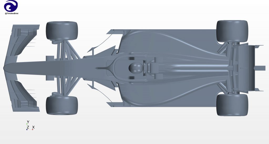
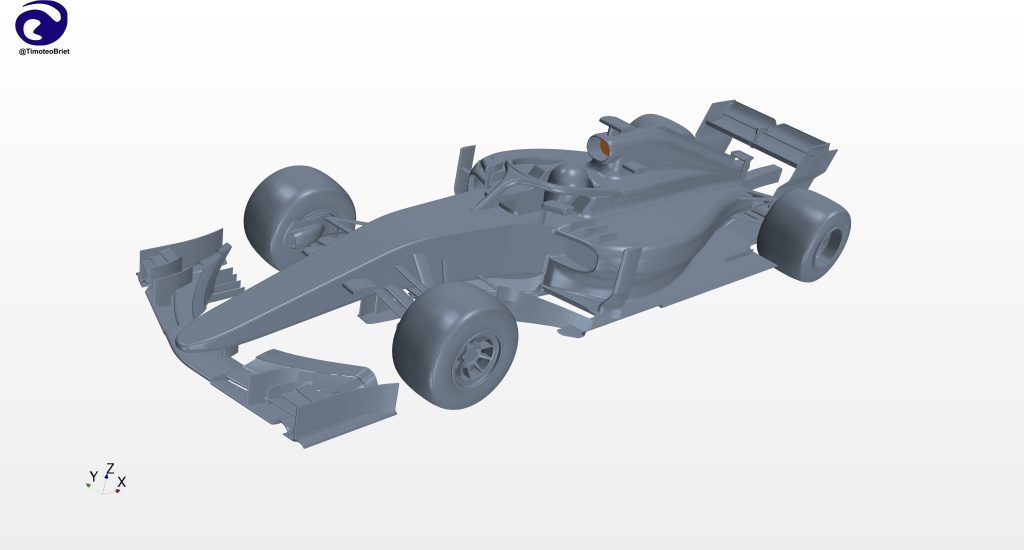
In order to compute the flow around a F1 body, we first need a volume which defines the fluid domain. Perhaps counter-intuitively, this is not the volume occupied by the car, but is in fact the “negative volume” of the wider area surrounding it. To accomplish this, we usually begin with a simple exterior shape (e.g. a rectangle), place the positive geometry of the car within it, then subtract the intersection of the two.
A Computer-Aided Design (CAD) model of the car which is appropriate for CFD is typically much less complex in comparison to one used for manufacturing, for example. Surfaces are often joined, gaps are closed, and detailed geometric features like bolts, wires and cables may be removed to facilitate simulation.
Once the fluid domain has been defined, the process of breaking up the continuous volume into a finite number of points (or volumes) is called “discretization.” This is a crucial step in the F1 CFD process, often requiring more time and effort than computing the solution itself. Once a suitable fluid volume has been defined, the result of the discretization is called a “grid” or a “mesh.” The numerous simple shapes which comprise the mesh can vary, but are usually some combination of hexahedra, tetrahedra, and general polyhedra.
A mesh not only provides the specific locations in space where the solution is to be computed, but also the necessary information about connections between points to be used in the fluid solver. The mesh not only suffuses the entire fluid volume, but also extends down to every exposed surface in the volume and can be quickly visualized in a “surface mesh,” an example of which is shown below.

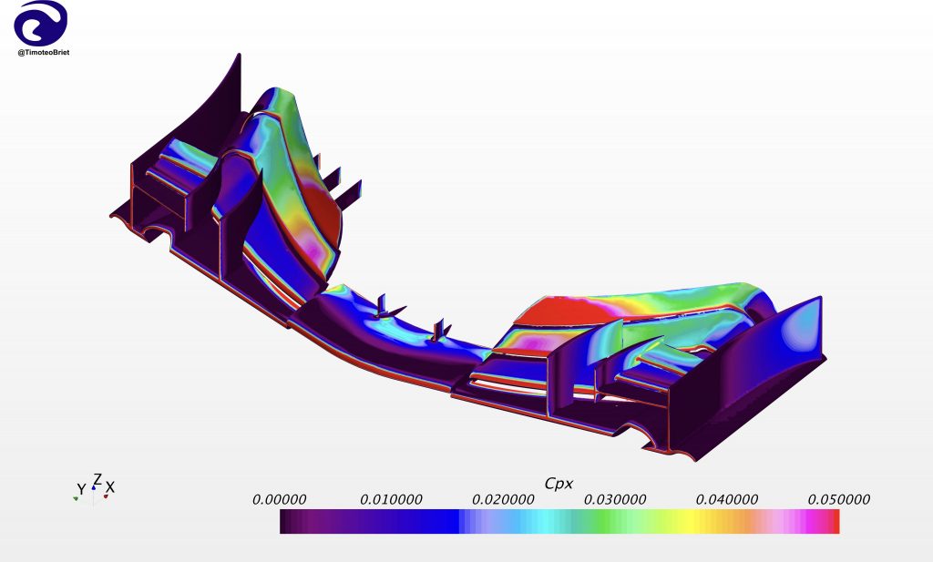
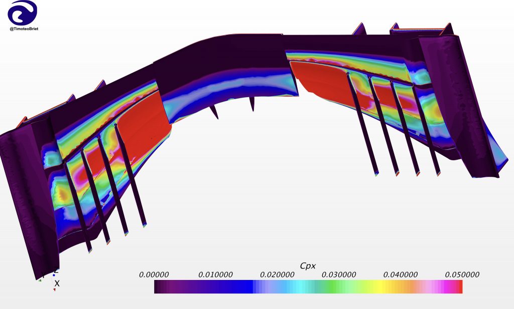
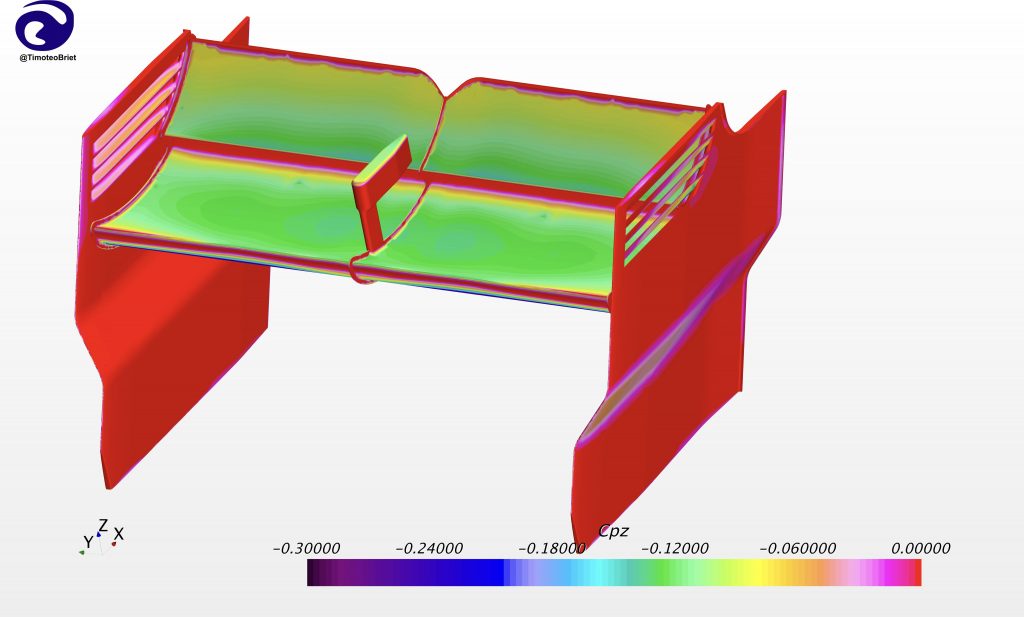
Importantly, the mesh must have a sufficient number of points packed into regions where key flow features will need to be resolved. Examples include the front tyre wake, Y250 vortex, rear tyre squirt, and leading edge separation bubble at the front lip of the floor. The precise details of the schemes used to numerically solve the Navier-Stokes equations are beyond the scope of this article, but the result of the CFD analysis is a complete solution flow-field where the pressure, velocity, temperature and density of the fluid can be determined at any point in the fluid domain.
Representing the flow solution as a large number of discrete values (often hundreds of millions of points) allows us to very accurately estimate quantities like the downforce, drag, and aerodynamic balance of the car by analyzing the associated pressure and velocity fields.
A key feature of simulating real-world flows is the modeling of turbulence. If you’ve ever seen smoke rising in the air, you have probably seen a turbulent flow. Turbulence is defined by chaotic velocity fluctuations in space and time which increase mixing, wall friction, and heat transfer. Although turbulent flows appear random at first glance, they actually have stable and very well-defined statistical properties. The flow around an F1 car is dominated by such turbulent flows, from the wake coming off of the tyres to the boundary layers growing along the body surfaces. A critical necessity of any successful CFD software package is the ability to accurately simulate these flows and the impact they have on downstream components.
Turbulence is an inherently unsteady process which occurs over a very large range of length scales. In order to compute the turbulent flow-field, a decision needs to be made about how to model the unsteady fluctuations. A process called Reynolds averaging, when applied to the Navier-Stokes equations, adds terms to the steady governing equations that account for these turbulent stresses. These Reynolds-Averaged Navier-Stokes (RANS) simulations are attractive because they are reasonably accurate and computationally very inexpensive.
A more accurate solution can be found by computing a full unsteady simulation and then time-averaging afterwards. This typically requires a spatial filtering of the turbulent fluctuations, to directly resolve the largest sizes but use a sub-grid model for the effects of fluctuations smaller than the mesh size. This is called “Large Eddy Simulation” (LES) and can be more accurate than RANS simulations but is much more expensive. Teams use each of these simulations for solving different types of aerodynamic problems.
One of the things that makes CFD so powerful is that a huge number of geometries can be tested to evaluate aerodynamic performance more quickly and less expensively than through using a wind tunnel or track testing. If performed in parallel, full simulations of dozens (if not hundreds) of geometries can be simulated in days and their aerodynamic performance compared to find the best solution.
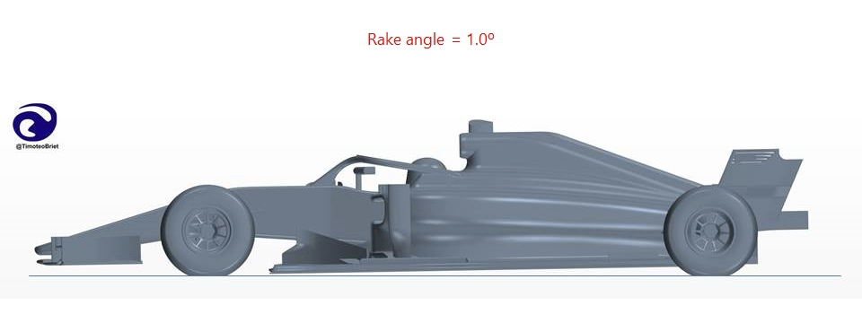
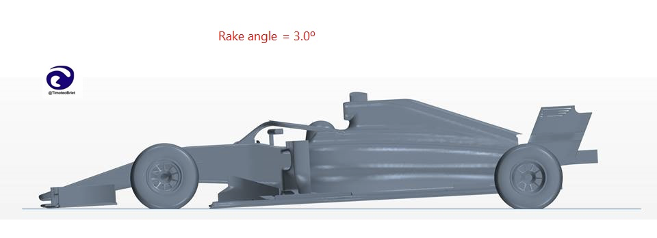
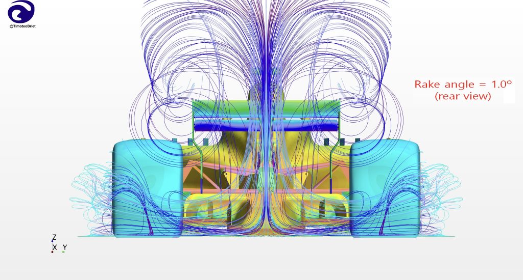
With the F1 cost cap in effect for this year, however, teams are limited to simulating approximately 1800 new geometries over an 8-week period (about 50 geometries per work day) according to Matthew Sorrell, Head of Aerodynamic Tools and Methods at Red Bull. Note also that “geometry” in this context can mean the same physical shape but in a different orientation. For example, teams may want to understand the effect that changing the car rake has on drag and downforce, as was likely the case after the significant floor changes made for 2021. CFD makes this a relatively painless process, amounting to simply modifying the pitch angle of the car CAD model.
Simulations can of course be incorrect (in fact notoriously so), but with frequent benchmarking, proper user training, and robust workflows, a high degree of confidence can be achieved in the simulation results. Not only is CFD very useful for simulating static car conditions, but it is also extremely useful for simulating dynamic events, such as the closing of the DRS flap. It is a well-known result from theoretical aerodynamics that instantaneous changes in the angle of attack of a wing do not result in instantaneous changes in the lift force.
Thus, if the F1 aerodynamicists wish to precisely understand how their wing designs perform when closing the DRS flap, they can run an unsteady CFD simulation to quickly figure out the downforce profile of the wing as a function time. This kind of dynamic test can be difficult to do in a wind tunnel, and potentially disastrous to test on track if the new specification wing does not maintain attached flow, as happened in Marcus Ericsson’s 220mph crash at Monza in 2018.
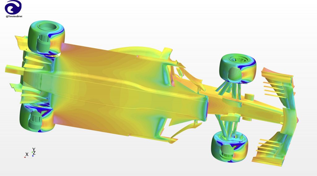
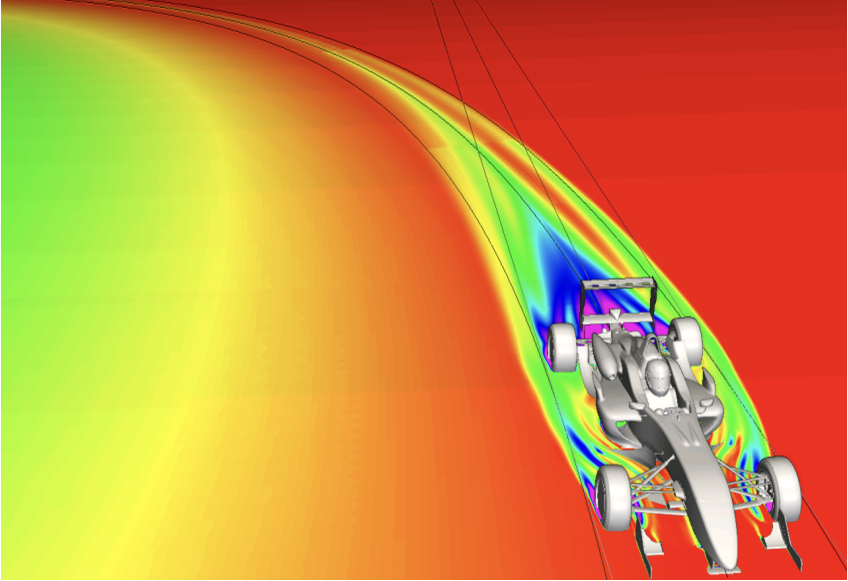
As was mentioned previously, CFD gives aerodynamicists access to the entire flow-field, not just information at specific locations in space. This makes possible detailed visualization of the flow in ways that simply are not possible with on-track tests or even in the wind tunnel. Access to the full velocity field, for example, allows the path of individual flow structures (such as vortices) to be tracked directly, such that downstream aerodynamic devices can be perfectly tailored to work in conjunction with them for maximum beneficial effect on the performance of the car.
This can be critical for understanding not only the performance of the car itself, but how it affects the flow on cars behind and how it in turn is affected by other cars ahead. Multiple car simulations are regularly performed in CFD to evaluate not only vehicle performance, but also how the cooling systems are affected by running in dirty air. Flow through radiator and brake ducts can also be evaluated using CFD, with the results used directly to help make decisions on inlet and outlet aperture sizing.

Finally, it is worth noting that CFD can provide some information about the flow around an F1 car that cannot (even theoretically) be gained from wind tunnel testing. Recall that the point of adding downforce is to provide additional grip when cornering. Yet, when we test the scale model of the car in the wind tunnel we test in a straight line or, at best, we give the car a uniform yaw (i.e. sideslip) angle by rotating the vehicle relative to the freestream. An actual cornering F1 car, however, does not experience a uniform yaw angle across it’s length.
The precise distribution depends on the steering geometry and relative slip between the front and rear axles, but it is definitely not uniform. Another way to think about the problem is that the wake of an F1 car that is angled in the wind tunnel travels straight backwards, while in the real application it follows the curved path of the car.
Moreover, simply angling the walls of the wind tunnel in an effort to replicate the effect will introduce an unrealistic variation in pressure across the tunnel that’s not present in the real flow. If the trajectory of the overall wake is not correct, it’s reasonable to assume that the fine details of the flow structures around the car are also not as representative as they could be.
CFD can be especially potent here, as the effect of the turning of the car can actually be simulated correctly by adding source terms to the Navier-Stokes equations which account for the acceleration of the vehicle. In engineering vernacular, CFD can directly account for non-inertial effects on vehicle aerodynamics better than a wind tunnel can. Not only is this beneficial for improving the simulation accuracy of steady-state cornering maneuvers, but it also allows for accurate simulation of traditionally difficult aspects of the corner like turn-in.
So, what is CFD? It is an extremely powerful computational tool which allows for the rapid aerodynamic evaluation of complex geometries over a wide range of dynamic operating conditions. Used on conjunction with wind tunnel and track testing, CFD allows aerodynamicists to refine their designs with a precise understanding of what impact these changes will have downstream, not only on their own car but on the other cars around them. CFD is not a magic box into which all problems can be thrown, but when used correctly it can be one of the most impactful tools of the F1 aerodynamicist.
SimScale: https://www.simscale.com/forum/t/f1-aerodynamics-tutorial/66446
TotalSim: https://www.totalsimulation.co.uk/cornering-flow-for-openfoam/